Flowchart Wizard
The Flowchart Wizard is a tool that transforms a sheet of text into a flowchart in just a few steps. With it, you can enter all the process steps into worksheet cells, and the Flowchart Wizard will load all the text into a form that lets you assign symbol types, formatting, and flow line routings to each process step. It will then generate a flowchart from that information. You may need to make some adjustments to the flowchart layout and flow line routings, but overall it cuts the time to create a flowchart considerably.
Pre-Layout
Before running the wizard, layout the text for the flowchart on the sheet. The picture below shows a sample worksheet with the text for the process steps entered into cells. When you enter the process text, the goal is to arrange it roughly how you want the flowchart to be organized. The wizard allows for two types of input - normal (shown below) and parsed, which allows for advanced control over connector routings. (See Parsing Rules for more detail.)
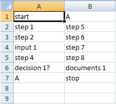
Picture 1 - Sample Flowchart Text
Running the Flowchart Wizard
Click Flowchart Wizard > Flowchart Wizard on the toolbar to launch the wizard. The first page of the wizard dialog allows to set some preferences for the flowchart.
Step 1 - Set Options
- Text Input Source: FlowBreeze gets the text for the flowchart steps off of the currently open worksheet. If you only want to use some of the text, click "Only text from range" and then select the range to import the text from.
- Template Settings: If you are using a swim lane template, this option helps ensure that the flowchart will be generated in the current lanes. See using the Flowchart Wizard with Templates page for more details.
-
Input Text Options:
- Ignore Keywords: If checked, all entries will be set to Process symbol types (i.e., rectangles) by default.
- Replace | character with line break: When checked, the wizard will put a hard line break wherever "|" is encountered. (The | character is commonly called a "pipe" and is located above the "\" character on the keyboard.)
- Add default decision branch labels: If checked, the default branch labels specified in the Settings will be added to the output. If branches are specified in either the input text or the connector section of Step 2 (below), then the defaults will not override them.
-
Flowchart Layout:
- The "Top to bottom" and "Left to right" options determine the default routing direction of the connectors.
- Uniform Symbol Height: For left to right flowcharts, you can choose to make all the symbols the same height.
- Connector style: Choose the style for the connector lines from the drop down. (The styles for the shapes are set in Step 2 of the wizard.)
-
Spacing Between Shapes:
- The Rows and Columns settings specify the minimum spacing between shapes.
- If you are using a swim lane lanes, the Columns setting is ignored for vertical swim lanes, and the Rows setting is ignored for horizontal swim lanes.
- Selecting "Keep existing layout" will prevent the wizard from adding any additional spacing between shapes.
-
Output Location:
- You can choose to output to the current worksheet or have FlowBreeze generate the flowchart in a new sheet, preserving the original content.
- If you overwrite the existing sheet, you can check the option to keep the existing shapes. This is useful when using templates with the wizard.
- Link shape text to input cells: If checked, the content of each shape is linked to it's original cell. If the text in the cell is changed, the shape's text will update automatically.
Step 2 - Set Symbols, Styles, and Connectors
When you click Next >, the Flowchart Wizard will display all the entries in Step 2. This step allows you to edit the text, change the symbol type, change the style, and add connectors and branch labels for each entry.
Entry list
- ID: This column is for reference when setting the Connectors. If you do nor use the advanced parsing syntax, the ID numbers will auto-generated.
- Symbol: This column shows the symbol type assigned to the entry.
- Style: This column shows the style assigned to the entry.
- Text: This is the text that will be placed into the symbol. If any mistakes were made on the original sheet, they can be corrected here.
Edit Symbol and Styles
Beneath the entry list are two images showing the symbol and the formatting style for the currently select entry. Clicking the button beneath either will prompt for a new symbol or style, respectively.
Connector Arrows
This list allows you to specify outgoing connectors for each item. When you click the + button, a new line is added to the connector list, with the following fields:
- Connect To: Allows you to set the ID to route a connector arrow to.
- Side: Specify the side the connector will be routed from. (required if branch label is set, otherwise optional)
- Branch Label: Specify a label placed next to the connector. (optional)
Generate flowchart
Click OK and the wizard will generate a flowchart. Some shapes may need to be repositioned to achieve the layout you desire.