Work with Flow Lines (Connectors)
Terminology
In flowcharting, an arrow from one process step to the next is often called a "Connector", a "Flow Line", or simply an "Arrow". As the names indicate, they show the direction of process flow. This help file uses the terms "Connector" and "Flow Line" interchangeably. In Excel, there are Arrows that do not stay attached to shapes, as explained below. Also, "Connector" means two things in Excel - a line that stays connected to a shape and also as the term used to describe symbols that show a jump from one part of the flowchart to another. These two symbols are called On-Page Connectors and Off-Page Connectors, labeled "A" and "1", respectively, in Picture 1 below.
![]()
![]()
Picture 1 - On and Off-page Connectors
(Do not confuse these types of "Connectors" with flow line "Connectors")
Flow line connectors vs. standard arrows and lines
Because of the possible confusion caused by using the word "Connector" for both connecting arrows and two symbol types, the FlowBreeze documentation will try to stick to using the term "flow line". That said, there is one instance when using the term "Connector" makes sense. That is to differentiate between an arrow that "connects" to a shape and a standard line or arrow that does not. (N.B.: starting with 2007, Excel no longer has arrows that don't connect to shapes.) A flow line "connector" will attach to a shape. When the shape is moved, the connector will stay attached to the shape whereas a standard line or arrow will not. To tell whether a flow line is connected to a shape, click on it and you should see a red dot at the connection points, as shown in the image below.
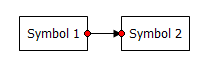
Picture 2 - Connected Flow Line
If one or both of the flow line end points has a green dot when selected (shown below), then it is not connected to the shape. If Symbol 2 were moved, the flow line will not be moved with it. To re-connect a flow line like this, click on the green dot with your mouse and drag it to a connection point on the shape.
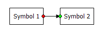
Picture 3 - Unconnected Flow Line
Each symbol type has preset connection points. When you position the mouse over a symbol, the cursor will change from an arrow (or cross hair ![]() if you are adding a new flow line manually) to a bomb site
if you are adding a new flow line manually) to a bomb site ![]() and the connection points will show as blue dots on the symbol border as shown in Picture 4 below.
and the connection points will show as blue dots on the symbol border as shown in Picture 4 below.
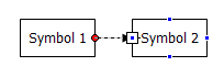
Picture 4 - Connection Points
Flow line connector types
There are three types of flow lines that you can create with FlowBreeze - straight, elbow, and curved, as shown below. The elbow connector is the default in FlowBreeze because it renders as a straight line when the symbols are aligned.
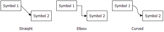
Picture 5 - Flow Line Styles
Changing flow line connector types
You can change the type of flow line by right-clicking on it and selecting the new type as shown below in Picture 6.
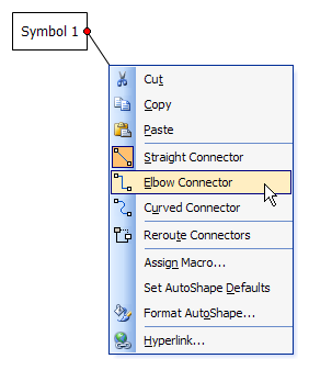
Picture 6 - Change Flow Line Type
(This menu is slightly different in Excel 2007+)
Rerouting Flow Lines
To change the routing of a flow line, you can click on an end point and drag it to a new connection point (while holding the left mouse button down). Also, you can use Excel's built-in "Reroute Connectors" function, shown above in Picture 6. This function will pick the shortest route between two points, so if there are any shapes between the two target shapes, there is a good chance that the flow line will be routed behind one of them. In such a case, it's easier to manually drag the end point to the new connection point.
You may find a layout where the flow lines don't line up as you would like them to. For example, in picture 7 below, the layout would look better if the flow line from Symbol 1 to Symbol 2 was in vertical alignment with the flow line from Symbol 3 to Symbol 2. To adjust the routing, first click on the flow line. A yellow diamond "handle" will appear. You can click on the yellow handle and drag the routing to a new position (as always, while holding the left mouse button down). The new routing will show as a dashed line while you drag the adjustment handle.
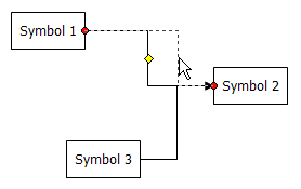
Picture 7 - Flow Line Adjustment Handle
See Also: How to Snap Objects for an example of routing one flow line to connect to another flow line.
Snapping A Connector to Another Connector
A common goal of FlowBreeze users is to route a connector line so that the end point connects to another connector arrow. The Excel lines do not have the capability to connect to other lines. This section shows two other options.
Option 1 - Use Snap to Grid
It's natural to assume that "Snap to Shapes" will allow you to snap one connector line to another, however, the "Snap to Shapes" setting will snap lines to all shapes except other lines. The best alternative is to use "Snap to Grid". (FlowBreeze uses the built-in "Snap to Shapes" and "Snap to Grid" Excel tools, but it doesn't have control of their behavior.)
- Toggle on "Snap to Grid".
- Drag the step 1 - step 3 connector end point to the desired position.
- Right-click on the connector and select Format Shape from the context menu.
- Click the Line Style option in the lane pane of the Format Shape dialog.
- Using the End Type drop down, change end point from an arrow to a straight line segment.
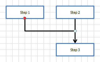
Snap connector to grid
Option 2 - Add a Connector Node
- Click Add Shapes to open the Add Shapes dialog.
- Add a circular Connector Node shape.
- Reroute existing lines to feed into connector node.
- Add new connector line from node to step 3.
- Resize connector node as needed for alignment.
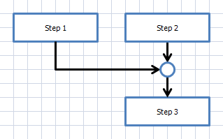
Connector snapped to node shape
Adding a Jog or Jump to a Flow Line
Unfortunately you can't. Some drawing tools allow you to add a jog to a line to indicate a crossover, as shown in Picture 7.
Picture 7 - Line Jog
Excel doesn't have this capability, and therefore neither does FlowBreeze. However, there are workarounds. One method is to use the Split Connector tool to replace the flow line with two connector nodes. Another method is shown below in the picture below. If you have a confusing routing (as shown on left), you can change one of the line types to Curved to make the routings clearer. See the Changing Flow Line Types section above for how to do this.
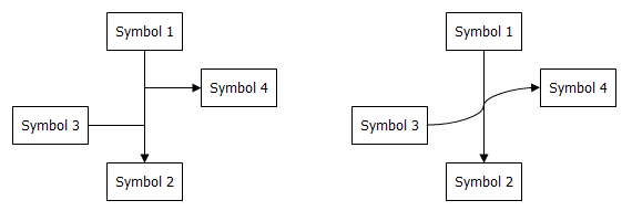
Line Jog Workaround