Interactive Flowcharting Tutorial
This tutorial will take you through the steps to create a flowchart using the interactive flowcharting mode of FlowBreeze. Because FlowBreeze is an Excel add-in, it will load with Excel but the interactive text-to-flowchart generation remains idle until you start a flowcharting session. It will operate on only one worksheet at a time, so you can start a flowcharting session and switch over to another worksheet without fear that it will inadvertently generate a flowchart symbol any time you edit the sheet.
Terminology
- Flow Line Connector vs. Connector Node: The word "connector" is often used to mean the arrow that joins two shapes. However, it is also the name for the nodes that show a jump from one place in the flowchart to another. To disambiguate between the two meanings, connector arrows are typically called "flow line connectors" or just "flow lines".
- Symbol vs. shape: The two terms are used interchangeability in the help file and in FlowBreeze dialogs.
Start the flowcharting session
- The first step to creating a flowchart is to click the Start button. If you're running the trial version, you'll be greeted by a trial reminder and will need to click the "Continue" button.
- You will be prompted with the Start Flowcharting window. Click OK. (For this tutorial, we will keep all of the default settings. For more information on the options, see the Start Window section.)
- FlowBreeze will generate a Terminator symbol, as shown below.
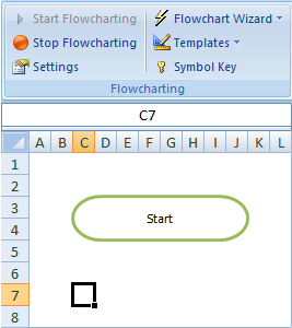
Terminator symbol added
The cursor is positioned below the symbol, ready for the next entry. Also, the Start Flowcharting button is now disabled and the Stop Flowcharting button has become enabled.
Add symbols
FlowBreeze watches for changes in worksheet content to generate symbols. Anytime you edit a cell, that will trigger a "change event". These change events are what FlowBreeze monitors to know that it needs to kick into action. In this step, we will show you three things:
- Using the basic text-to-symbol technique.
- Creating a symbol using a keyword.
- Creating a symbol using a prefix.
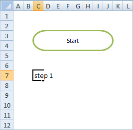
Type "step 1" into the cell and press Enter. As show below, FlowBreeze generates the default flowchart symbol - a process shape (rectangle). Also note that the first letter of "step 1" was automatically capitalized.

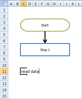
Next, we will generate a symbol using a keyword. Keywords are special words that you assign to symbols and can be customized in the Settings window. The word "read" is preset as a keyword for the data symbol, so you can type "read data" into the next cell to create the Data symbol, as shown below.

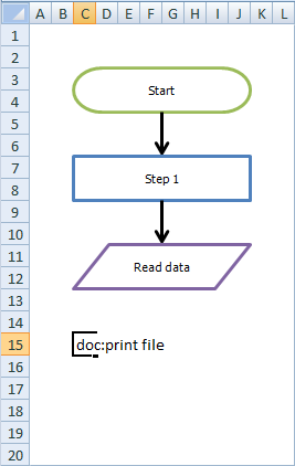
Now, we will generate a symbol using a prefix. Like keywords, prefixes are special entries that you assign to specific symbols and can be customized in the Settings window. Prefixes are placed at the start of an entry and must end with a "prefix delimiter". The delimiters can be customized on the General tab in the Settings window.
Enter "doc:print file" in the next cell. Since "doc:" is preset as a prefix for the Document symbol, the prefix is stripped out from the entry and just the words "Print file" are placed in the Document symbol.

Creating a decision symbol
Decisions are symbols that indicate a fork in the process. One feature of FlowBreeze is that any entry containing a question mark (?) will generate a Decision symbol and branch labels, e.g., Yes/No, Pass/Fail, etc.
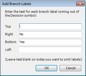
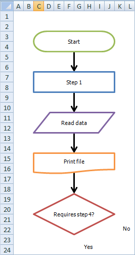
Enter the text "requires step 4?".
FlowBreeze will add the Decision shape and prompt to add branch labels. (Note the default right label is "No" and the default bottom label is "Yes"). The labels are then added next to the decision, as shown below. You can disable this feature or change the default labels in on the Decisions tab of the Settings window.
|
|
|
Manually adding labels
For the decision, you were prompted to add labels, but there are times when you might want to add a label yourself. These are covered in detail in the Insert a Label section.
Adding connector class="f_SubHeading">nodes
On-Page Connector nodes are circles that show a jump from one part of the flowchart to another. On the General tab of the Settings window, FlowBreeze can be configured to add a connector node when a 1 or 2 character ALL CAPS entry is made (e.g., A, B, AA, B1).
In the "Final sample flowchart" picture below, we added a "Step 4" in the same way we added "Step 1". Then we entered "A" in cell C30 (after Step 4) to create a connector node. The connector node is automatically centered to the shape above it.
We will now continue the flowchart in column Q of the worksheet. To show continuance, another node is added by typing "A" in cell Q3. Once again, the connector node is added and then centered based on the standard shape width. This will position the second A node in cell T3.
Adding Connectors (aka, arrows or flow lines)
In most cases, FlowBreeze will automatically detect the last shape and add the connector arrow. However, if FlowBreeze cannot detect which symbol you want to add a connector from, it will prompt you with the Add Flow Line Connector window. This short tutorial doesn't demonstrate that, but you can see the Flow Line Prompt section for more details.
In other cases, you may want to manually add a connector. To demonstrate, type "step 5" in cell Q7 to create a new shape. Now we're going to add a connector from the "No" branch of the decision "Requires step 4?" by using the Add Connectors task pane by following these steps:
- Click Add Connectors from the FlowBreeze toolbar.
- In the From Shape column, select "Requires step 4?"
- In the To Shape column, select "Step 4".
- Click the Add Connector button on the task pane.
A new connector will be added between the shapes, as shown in the "Final sample flowchart" picture below.
Stop the flowcharting session
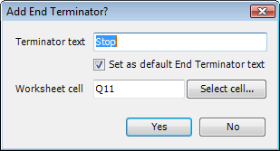
To end the interactive flowcharting session, click the Stop button on the toolbar. Before you stop flowcharting, it's a good idea to select the cell where you want to place the stop Terminator. FlowBreeze will use this as the default location to place the Terminator symbol. In our example, you will place it beneath "Step 5".
Upon clicking the Stop button, FlowBreeze will display the "Add End Terminator?" window, shown below. In this window you can change the text (with the option to make the new text the default for the next time you flowchart), and you can change the cell where the Terminator should be added by clicking the Select Cell button. When you click Yes, the Terminator is added and the flowcharting session is completed.
Once the session is topped, FlowBreeze will no longer generate symbols from your entries, meaning you can go back to using the worksheet for normal Excel activities.
Add end terminator window
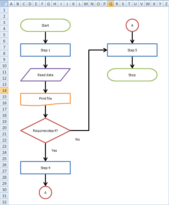
Final sample flowchart